Choosing the motor that best meets your application needs is important. When both stepper and servo motors fit
the needs of a positioning system, you should know the differences. This will help you make the right choice.
This article will explain the difference between stepper and servo systems.
We'll start by comparing the two motor technologies.
Stepper Motors vs. Servo Motors

Pros: Pros
Low-speed torque with good performance High-speed torque
No tuning, no hunting Peak torque available
Compact Motor Size Continuous Duty
Cost-effective Pack with Functions
Cons: Cons
Less high-speed torque Needs Tuning
Limitation of the duty cycle Works only with feedback
No peak torque Hunting
Open-loop loops are the most common The cost of the product
Both servo and stepper motors use permanent magnets for their rotors. To work, they also require drive circuits.
Their designs differ. The differences in their designs lead to different performance.
Motor Design
The system uses the encoder to guide a stepper motor to the desired position. You will first notice that a servomotor
requires an encoder. This increases its length.
Second, the difference in the number of poles. People call these poles "magnetic" poles, and they can either be north
magnetic poles or south magnetic poles. The poles are stable areas where magnetic fluxes from the stator can interact
with the rotating rotor.
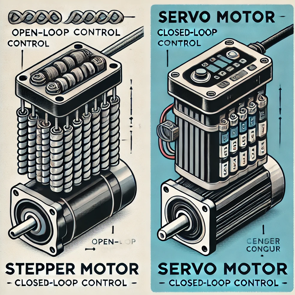
We'll have to dig deeper into the motor designs to understand how stepper motors differ from servomotors. Below,
the left image shows the stepper motor's construction.
Stepper Motor

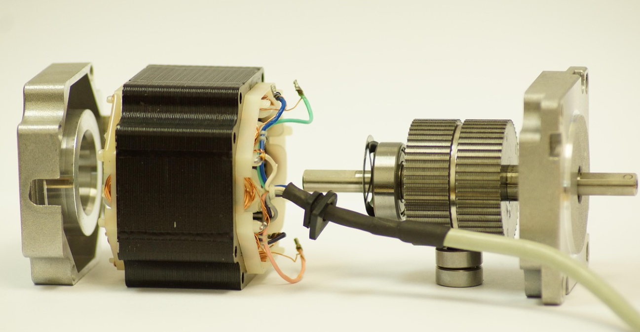
The stepper design uses a rare-earth permanent magnet sandwiched between two toothed rotor cups. The teeth
on the rotor cup become magnetized poles by axially magnetizing the permanent. The rotor can be either 100 or 50 teeth.
Both rotors are slightly angled at half the tooth pitch. Each tooth of the rotor cup becomes a pole for a stepper.
Servo Motor

In a servomotor (shown above), engineers use a radially magnetized rotor instead of teeth. This is why servomotors
are significantly smaller. The system requires encoder feedback to reduce errors caused by the low number of poles.
A typical servo design uses a 3-phase stator (U, V, W) and a rotor that has 28 poles. The rotor of the servo motor has
segments with permanent magnets. This is different from a stepper motor, which has an axially magnetic rotor.
Stop Accuracy
The motor’s accuracy in stopping is a primary requirement for positioning applications. A stepper motor or a servomotor
can both stop with accuracy.
The accuracy of a stepper motor relies on its electrical winding and the design of its teeth. A servo's accuracy depends on the
quality of its construction, the encoder, and the algorithm used. The only friction between the stator and rotor comes from
the ball bearings. Friction torque or even gravitational loads can affect the actual stopping position.
Stop accuracy depends on several factors. These include the winding properties, the quality of the rotor's construction, and
the number of poles or teeth on the rotor. Assembly accuracy, encoder resolution, and the operating algorithm determine
the stop accuracy for a servomotor.
You can think of a stepper as a device designed for mechanical positioning. A servo is made for the same purpose, but in an
electrical way.
High Speed Performance
The servo motor is known to run at higher speeds. This means that a servo will produce more torque for a given RPM than
a stepper motor.
The difference between servo and stepper motors comes from their pole counts and inductance. The number of poles can
affect how many turns the motor's winding needs to make for one full revolution. It may only take 12 "steps" for a motor
to complete a revolution. For a two-phase motor, however, 200 "steps' are required.
This doesn't matter at low speeds. At high speeds, the driver won't be able to fully energize the coils. Because torque is
proportional to current, torque will decrease at higher speeds.
High Speed Performance
Servo motors are generally known for running higher speeds than stepper motors. What this really means is that the servo
motor will output more torque at a specified RPM than a stepper motor. The difference in torque performance comes from
the pole count and winding inductance in servo and stepper motors.
The number of poles also affects the number of times a motor winding needs to be advanced for a full motor revolution.
For a servo motor, it may take only 12 "steps" to advance a full revolution. However, it takes 200 "steps" for a 2-phase
stepper motor.
At low speeds, this doesn't make a significant difference. However, at high speeds, the driver will not be able to fully energize
the windings. Since current is proportional to torque, the torque decreases at high speeds.
The performance difference between stepper motors and servo motors can be best shown by their speed-torque curves.
Stepper motors with a high pole count can start quickly and smoothly run at low speeds. The motors can be positioned
quickly.
They respond fast and generate holding torque. They do this without needing an encoder. The L/R constants and high
pole count of winding inductances reduce torque in high-speed regions.
Servomotors have a low pole count and winding inductance. This means they create low starting torque. However, they keep
this torque better at all speeds.
Closed Loop Feedback
A servomotor must operate in closed-loop mode by definition. Typically, users operate stepper motors with an open-loop
system. A servomotor uses feedback to control its position, speed, or torque.
You can tell the stepper motor to move in a certain direction without feedback. However, an overload might cause it to lose
sync.
The driver gets more complex with the feedback system to stay in sync. A servo system has a pulse generator, a phase
sequencer, and an FET for a stepper motor. It also has an F/V converter, current amplifier, speed amplifier, position amplifier,
and deviation counter. You need all of these parts to run the motor in a PID loop. The driver checks for errors and adjusts
the proportional, integral, and derivative gains for corrections in real time. These are the reasons why servomotors cost
more and require processing time.
Along with closed-loop feedback, the motor's load-to-rotor-inertia-ratio also increases. A stepper motor can manage
about 10 times its rotor inertia. A servo motor can manage 100 times its rotor inertia. As a comparison, a closed-loop
stepper motor can handle 30x its rotor inertia.
Stepper motors operate without the need for feedback, so they require fewer components to operate. This is why they're
more cost-effective. Servo motors require feedback and operate in a PID loop, therefore, more components are necessary.
Efficiency
The stepper motor uses a current-chopper driver, which ensures a constant supply of current regardless of the load. The
duty cycle of a stepper is limited by the temperature.
The Servo Motor is better at controlling current. It only uses the amount of current it needs. Stepper motors are better at
generating holding torque when the speed is zero. The holding torque generated by servo motors is higher.
Efficient current control also leads to improved performance, including reduced noise and vibration. Size motors correctly.
When stepper motors are not properly sized, they tend to vibrate a lot more. If it is not correctly sized and tuned, servo
motors will "hunt".
The closed-loop control also makes current management more efficient. This helps keep motor temperatures lower and
extends their life.
Observe how the temperature increases with duty. It is for this reason that stepper motors need to have a limited duty cycle.
Temperature affects the life expectancy of bearing grease, which is what determines the service life.
Servo systems can draw only the current they need. This advantage helps increase their lifespan, reduce noise in some cases,
and lower power use. A stepper must close the loop to provide the same level of current control.
 中文版
中文版 English


